TI MSP-FET — Setup
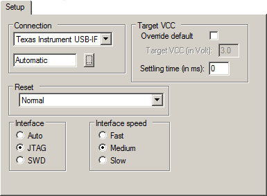
The Setup options specify the TI MSP-FET interface.

Connection
Controls the communication between C-SPY and the target device.
The C-SPY TI MSP-FET debugger can communicate with the target device via a number of different debug probes. Select the probe you are using. If you select Automatic, the debugger will automatically connect to the correct port.
Some emulator drivers support multiple emulators connected to the same host computer. Each emulator requires its own instance of IAR Embedded Workbench and each instance must identify its emulator. To identify an emulator, click the browse button to display a list of all detected emulators. To identify a connection, click the port in the list and the Mode LED on the attached emulator will light up.
Target VCC
Specify the voltage provided by the USB interface:
- Override default
Overrides the default voltage. The default voltage is displayed in the Target VCC text box, when you deselect the Override default option.
- Target VCC
Specify the voltage with one decimal’s precision in the range 1.0-4.0 V. This option can only be used when your target device is powered by the debug probe.
- Settling time
Specify a delay (in milliseconds) that will be used between switching on the target VCC and starting the identification of the Arm device.
Note
User-defined millisecond timeouts and delays are generated using the host operating system clock ticks. Because the host operating system is not a real-time OS, the actual delay or timeout will vary each time with approximately 5–20 ms.
Reset
Selects the reset strategy to be used when the debugger starts.
- Normal (0)
This is the default strategy. It does whatever is the best way to reset the target device.
Interface
Determines the debug interface to use:
- Auto
Selects the debug interface automatically.
- JTAG
Selects the JTAG interface.
- SWD
Selects the SWD interface. SWD uses fewer pins than JTAG.
Interface speed
Sets the JTAG communication speed. Choose between Fast, Medium, and Slow.