Hardware Setup dialog box
The Hardware Setup dialog box is available from the C-SPY Driver menu.
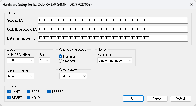
Use this dialog box to configure the hardware debugger.
CPU mode
Selects the CPU mode. This option is locked to Single chip.
Requirements
A C-SPY hardware debugger driver.
Security ID
Specify the ID code for CPUs that are read-protected with an RSU ID code, a 32-digit or 64-digit (depending on device) hexadecimal number. By default, all digits are F. When authentication fails, a connection error will occur.
Code flash access ID
Specify the access code for reading the code flash memory, a 64-digit hexadecimal number. By default, all digits are F. When authentication fails, a connection error will occur.
Data flash access ID
Specify the access code for reading the data flash memory, a 64-digit hexadecimal number. By default, all digits are F. When authentication fails, a connection error will occur.
Main OSC
Selects the frequency of the clock oscillator before it is multiplied internally in the CPU.
Rate
Selects the multiplication rate of the main clock oscillator.
Sub OSC
Selects the frequency of an optional low frequency clock.
Peripherals in debug
Controls the status of the peripheral units when the application stops. Choose between:
- Running
Makes the peripheral units keep running when the application stops.
- Stopped
Makes the peripheral units stop when the application stops.
Power supply
Selects the source of power supply for the target board. Choose between:
- External
An external source supplies power.
- 3 V
The E1/E2/E20 emulator supplies 3 V of power.
- 5 V
The E1/E2/E20 emulator supplies 5 V of power.
Map mode
Specifies the map mode for the code flash memory. Choose between:
- Single map mode
Specifies device support for hardware remapping of the user area read address supported by GCFU (overlay function).
- Double map mode
Specifies device support for hardware swapping of the address map between code flash memory banks. The banks are mapped into one valid area and one invalid area.
For more information, see the device hardware documentation.
Pin mask
Selects the non-connected pod pins, so that they do not disturb the execution of the CPU. If the RESET option is selected, the pod pin is not connected.