Hardware Setup
To display the Hardware Setup dialog box, click to the left of the Hardware Setup command on the Emulator menu when C-SPY is not running, to place a checkmark next to the command. The next time you start C-SPY, the dialog box will be displayed. See Emulator menu.
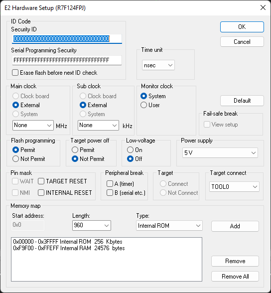
Use this dialog box to configure the emulator. Not all options are available for all emulators.
ID Code
Specify the security ID codes for devices that are read-protected with an ID Code.
Security ID | Specify the security ID for reading codes in the internal ROM or internal flash memory. This is a hexadecimal number of 20 digits (10 bytes) or 32 digits (16 bytes). By default, all digits are zero ( |
Serial Programming Security | Specify the serial programming security ID. This is a hexadecimal number of 32 digits (16 bytes). By default, all digits are |
For examples about how to define the security ID, see Security ID and option bytes.
Time unit
Selects the time unit to be used in the Trace View window, the Function Profiler window, and by the TIME registers in the Registers window.
Main clock
This is the main clock source input to the CPU. The main clock is always set to External and cannot be changed.
Sub clock
This is the sub clock source input to the CPU. The sub clock is always set to External and cannot be changed.
Monitor clock
Controls the operation clock of the monitor program. System configures the monitor program to be executed using the main clock. User configures the monitor program to be executed using the clock selected by the user application.
Fail-safe break
This option is not used.
Flash programming
Controls flash programming. Choose between:
Permit | Allows downloading to flash memory. |
Not permit | Prohibits downloading to flash memory. |
Target power off
Together with the Pin mask option TARGET RESET, this option controls the Power Off emulation of the target board. A reset operation will result in the following:
Target power off | Target reset | Result of reset operation |
|---|---|---|
Permit | Selected | No reset operation performed |
Permit | Deselected | Executes the application immediately after a reset operation |
Not permit | Selected | No reset operation performed |
Not permit | Deselected | Generates a break after a reset operation |
Low-voltage
Enables low-voltage flash programming down to 1.8 V.
Power supply
E1, E2, E2 Lite/E2 On-Board, EZ-CUBE2: Specifies the target board power. Choose between:
3V low voltage adapter | The emulator provides 3 V power. This option must be used for the S1 core with a low voltage adapter board. |
3V | The emulator provides 3 V power. |
5V | The emulator provides 5 V power. (Not available for the E2 Lite emulator.) |
Target | The board has its own power supply. |
E20, EZ-CUBE, TK, and COM Port: The power supply is always set to Target.
Peripheral break
Controls peripheral emulation. Choose between:
A (timer) | Stops timer-related peripheral emulation on break. |
B (serial etc.) | Stops peripheral emulation related to serial communication on break. |
Target
This option is not used.
Target connect
Selects the communication port between the emulator and the target board. The only available option is TOOL0.
Memory map
Use the Memory map options to change the predefined memory areas.
Unallocated memory areas, except the SFR area, are always set as guarded, which means that they are read- and write-protected. If an application reads or writes in guarded memory or writes in ROM, the execution is stopped.