Target interface
This section contains descriptions of pinout, signals, and connectors. The following cables are described in detail:
The JTAG/SWD - MIPI-20 cable
The JTAG/SWD - MIPI-10 cable
I-jet comes with a 6-inch cable with 20-pin MIPI connectors on both ends for devices with 20-pin MIPI headers:
The mating connector for a target board has the pitch size 0.05 in (1.27 mm). You can, for example, use part number SHF-110-01-L-D.
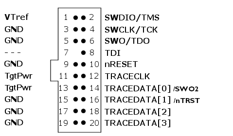
These are the MIPI-20 pin definitions:
Pin | Signal | Type | Description |
|---|---|---|---|
1 | VTref | Input | The target reference voltage. Used by I-jet to check whether the target has power, to create the logic-level reference for the input comparators, and to control the output logic levels to the target. It is normally fed from JTAG I/O voltage. |
2 | SWDIO/TMS | I/O, output | JTAG mode set input of target CPU. This pin should be pulled up on the target. Typically connected to TMS of the target CPU. |
3 | This pin is a GND pin connected to GND in I-jet. It should also be connected to GND in the target system. | ||
4 | SWCLK/TCK | Output | JTAG clock signal to target CPU. It is recommended that this pin is pulled to a defined state of the target board. Typically connected to TCK of the target CPU. |
5 | This pin is a GND pin connected to GND in I-jet. It should also be connected to GND in the target system. | ||
6 | SWO/TDO | Input | JTAG data output from target CPU. Typically connected to TDO of the target CPU. When using SWD, this pin is used as Serial Wire Output (SWO) trace port. (Optional, but not required for SWD communication.) |
— | — | — | This pin (normally pin 7) does not exist. |
8 | TDI | Output | JTAG data input of target CPU. It is recommended that this pin is pulled to a defined state on the target board. Typically connected to TDI of the target CPU. For CPUs which do not provide TDI (SWD-only devices), this pin is not used (tri-stated). |
9 | This pin is a GND pin connected to GND in I-jet. It should also be connected to GND in the target system. | ||
10 | nRESET | I/O | Target CPU reset signal. Typically connected to the RESET pin of the target CPU, which is typically called nRST, nRESET, or RESET. Bidirectional pin. By default an input that detects the board’s reset signal, but it can be configured as output and used for asserting a reset to the board. |
11 | TgtPwr | Output | This pin can be used for supplying 5 V power to the target hardware from I-jet. |
12 Not used | TRACECLK | Input | Input trace clock. |
13 | TgtPwr | Output | This pin can be used for supplying 5 V power to the target hardware from I-jet. |
14 Not used | TRACEDATA[0] / SWO2 | Input | Input Trace data pin 0. This pin can be used as secondary SWO. |
15 | This pin is a GND pin connected to GND in I-jet. It should also be connected to GND in the target system. | ||
16 Not used | TRACEDATA[1] / nTRST | I/O | Input Trace data pin 1. This pin can be used as nTRST. When the pin is used as nTRST, the signal is an output signal. |
17 | This pin is a GND pin connected to GND in I-jet. It should also be connected to GND in the target system. | ||
18 Not used | TRACEDATA[2] | Input | Input Trace data pin 2. |
19 | This pin is a GND pin connected to GND in I-jet. It should also be connected to GND in the target system. | ||
20 Not used | TRACEDATA[3] | Input | Input Trace data pin 3. |
I-jet also comes with a 6-inch cable with a 20-pin MIPI connector on one side (to connect to I-jet) and a 10-pin MIPI connector on the other side for connection to devices with 10-pin headers:
The mating connector for a target board has the pitch size 0.05 in (1.27 mm). You can, for example, use part number SHF-105-01-L-D.
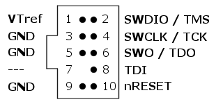
These are the MIPI-10 pin definitions:
Pin | Signal | Type | Description |
|---|---|---|---|
1 | VTref | Input | The target reference voltage. Used by I-jet to check whether the target has power, to create the logic-level reference for the input comparators, and to control the output logic levels to the target. It is normally fed from JTAG I/O voltage. |
2 | SWDIO/TMS | I/O, output | JTAG mode set input of target CPU. This pin should be pulled up on the target. Typically connected to TMS of the target CPU. |
3 | GND | GND | Connected to logic GND on I-jet. |
4 | SWCLK/TCK | Output | JTAG clock signal to target CPU. It is recommended that this pin is pulled to a defined state of the target board. Typically connected to TCK of the target CPU. |
5 | GND | GND | Connected to logic GND on I-jet. |
6 | SWO/TDO | Input | JTAG data output from target CPU. Typically connected to TDO of the target CPU. When using SWD, this pin is used as Serial Wire Output (SWO) trace port. (Optional, not required for SWD communication.) |
7 | — | KEY | KEY or GND |
8 | TDI/NC | Output | JTAG data input of target CPU. It is recommended that this pin is pulled to a defined state on the target board. Typically connected to TDI of the target CPU. For CPUs that do not provide TDI (SWD-only devices), this pin is not used (tri-stated). |
9 | GND | GND | GND and target detect presence. |
10 | nRESET | Output | nRESET or TRST |