Adapters
There are a number of useful adapters available. All of them are automatically recognized by I-jet. The following adapters are described in detail:
The ADA-MIPI20-ISO isolation adapter
The ADA-MIPI20-ARM20 adapter
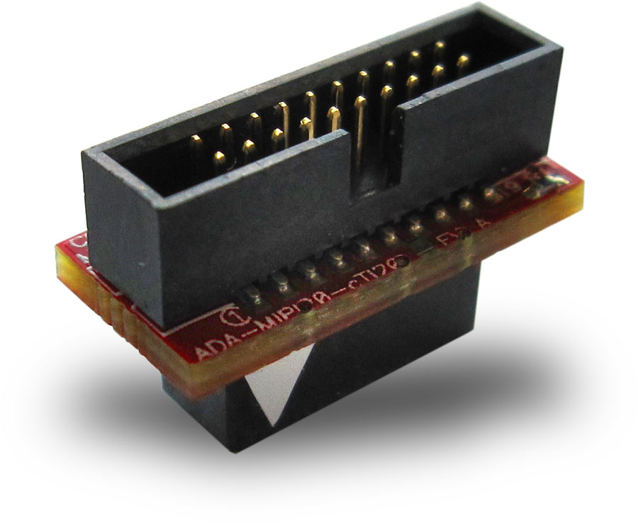
The ADA-MIPI20-TI14 adapter
The ADA-MIPI20-cTI20 adapter
The ADA-MIPI20-STSWD6 adapter
The ADA-MIPI20-RISCV12 adapter
Adapters not included in the I-jet package can be purchased from IAR.
These are the mating target headers for the adapters:
TI-14 | cTI-20 |
|---|---|
HTST-107-01-L-DV | TML-110-02-GD-SM-006 (shrouded) FTR-110-51-S-D-06 (unshrouded) |
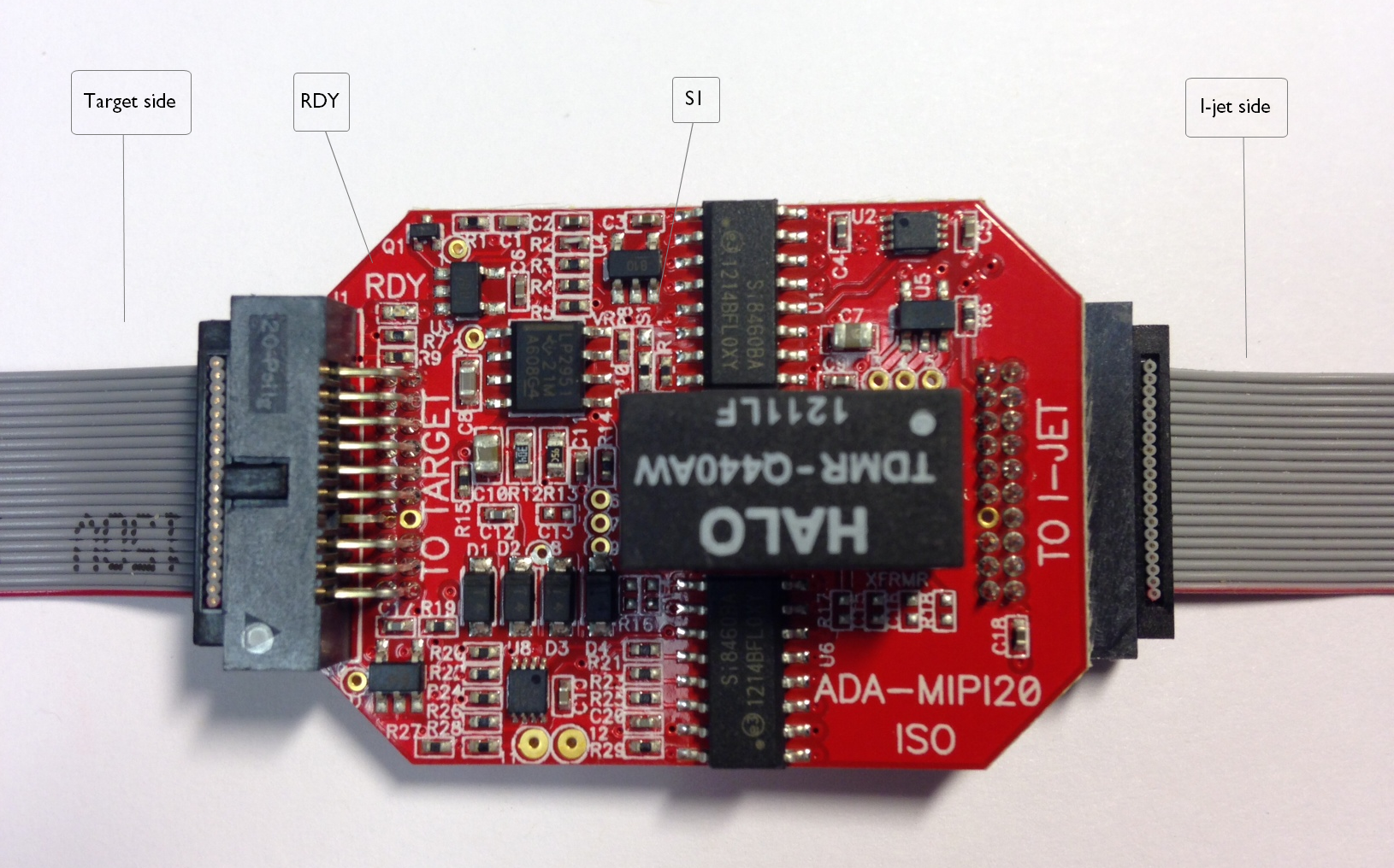
The ADA-MIPI20-ISO isolation adapter galvanically isolates signals between the I-jet MIPI-20 connector and the target MIPI-20 connector. You can use it to reduce the risk of damage to the I-jet debug probe associated with power ground loops, voltage spikes, electrostatic discharge (ESD), and noisy power and ground lines generated by targets which drive high-current motors and other machinery.
The adapter has two MIPI-20 headers marked TO I-JET and TO TARGET. Make sure to connect the headers correctly because switching the sides will not work and might damage the adapter. The target side of the isolation adapter can be used with any passive IAR I-jet adapters, for example, the ADA-MIPI20-ARM20, ADA-MIPI20-TI14, and ADA-MIPI20-CTI20 adapters, and the MIPI20-MIPI10 cable.
The adapter is automatically recognized by the IAR C-SPY® Debugger, and the adapter powers up and the green RDY LED is turned on.
Galvanic isolation up to 3000 V peak* (< 1 sec transients. See the Important safety and disclaimer note below) with continuous working voltage operation of up to 300 V.
Compatible with I-jet.
Supports the JTAG, SWD, cJTAG, and SWO debug modes.
Compatible with I-jet Trace in JTAG, SWD, cJTAG, and SWO modes only. (ETM/N-Trace is not supported.)
Powered entirely by I-jet via pins 11 and 13 on the MIPI-20 header.
The RDY LED indicates that the unit is powered and ready to use.
Supports target voltages from 2.5 to 5 V.
JTAG/SWD/cJTAG clock speed up to 32 MHz.
The adapter might not be automatically detected and powered by older versions of IAR Embedded Workbench for Arm. In such cases, select the Target Power option on the Project>Options>Debugger>I-jet>Setup page.
The adapter does not supply power to target and therefore does not resume the target power consumption.
When used with the ADA-MIPI20-TI14 and ADA-MIPI20-CTI20 adapters, the EMU0 and EMU1 signals are not connected.
Due to added JTAG signals propagation delays, some target boards might not work at the full 32 MHz JTAG clock speed, so reducing the JTAG speed in C-SPY might be needed.
The majority of Arm target boards have the SWO signal routed to pin 6 of the target MIPI20 debug connector. In cases when pin 14 is used for SWO, you must move the 0R shunt (marked S1) up from position 3–2 to position 2–1.
The adapter does not support 1.8 V JTAG signals from target. The target JTAG voltage range is limited to 2.5–5 V.
The JTAG interface on the target side automatically adapts to the voltage given on the target VTref pin (2.5 V–5 V). Because of the isolation barrier, the I-jet side uses its own voltage, independent of the target voltage. This is for information only and has no effect on the target JTAG operation.
ETM trace is not supported by this adapter.
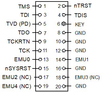
MIPI20 connector pinout on target side
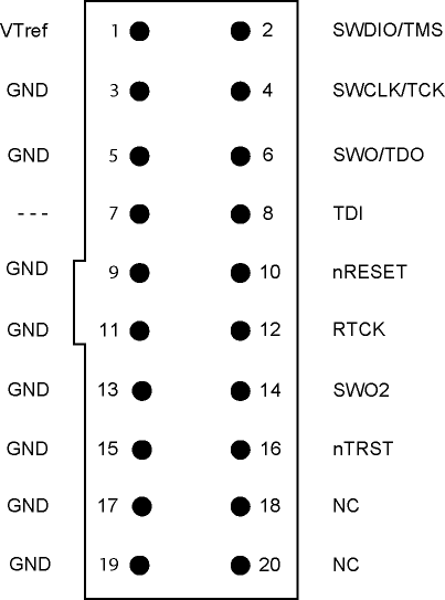
For more information about the signal descriptions, see Target interface.
Important safety and disclaimer note
The continuous normal operation voltage across the isolation barrier should not exceed 300 V DC.
The isolation voltage only represents a measure of immunity to transient voltages—the probe should never be used as an element of a safety isolation system. For use with higher continuous voltages, additional isolation/insulation systems must be used in accordance with the safety standard requirements.
Warning
When handling equipment subjected to high voltages, use caution and follow all safety regulations. Touching any exposed circuitry on the target, the adapter, cables, or the I-jet probe can cause injury or death.
IAR or the manufacturer shall not be liable for any damages related to the use of this probe.
The ADA-MIPI20-ARM20 adapter converts the MIPI-20 I-jet cable to the legacy ARM-20—0.1 in × 0.1 in (2.54 mm x 2.54 mm) pitch—JTAG headers. This is a diagram of the adapter:
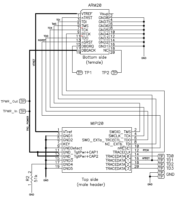
These are the pin definitions of the ADA-MIPI20-ARM20 adapter:
Pin | I-jet direction | Name | Description |
|---|---|---|---|
nTRST | Output | Test Logic Reset | Test reset. Active LOW signal that resets the TAP controller's state machine. |
TCK | Output | Test Clock | TCK synchronizes all JTAG transactions. TCK connects to all JTAG devices in the scan chain. TCK flows down the stack of modules and connects to each JTAG device. (IAR Embedded Workbench for Arm: However, if there is a device in the scan chain that synchronizes TCK to some other clock, then all down-stream devices are connected to the RTCK signal on that processor.) |
TMS | Output | Test Mode Select | TMS controls transitions in the tap controller state machine. TMS connects to all JTAG devices in the scan chain as the signal flows down the module stack. |
TDI | Output | Test Data Input | TDI is the test data input signal that is routed to the TDI input of the first device in the scan chain. |
TDO | Input | Test Data Output | TDO is the return path of the test data input signal TDI. In a multi-device JTAG chain, the TDO of the first device connects to the TDI of the next device, etc. The last device's TDO is connected to the TDO on the JTAG header. |
RTCK | Input | TCK Return | IAR Embedded Workbench for Arm: RTCK is a mechanism for returning the sampled clock to the JTAG equipment, so that the clock is not advanced until the synchronizing device captured the data. In adaptive clocking mode, I-jet is required to detect an edge on RTCK before changing TCK. In a multi-device JTAG chain, the RTCK output from a device connects to the TCK input of the down-stream device. If there are no synchronizing devices in the scan chain, it is unnecessary to use the RTCK signal and it is connected to ground on the target board. IAR Embedded Workbench for RISC-V: This pin is not used and is connected to ground on the target board. |
VTref | Input | Voltage Target Reference | This is the target reference voltage. It indicates that the target has power. VTref is normally fed from Vdd on the target hardware and might have a series resistor (though this is not recommended). VTref is used by I-jet to detect if target power is active and to set JTAG signal voltage reference for level translators. |
nSRST | I/O | System Reset | Active LOW open-collector signal that is driven by I-jet to reset the device and/or the target board. I-jet senses this line to determine when you have reset the device. |
Vsupply | Output | — | This pin is not connected to I-jet. |
DBGRQ | Output | — | This pin is not connected on I-jet. |
DBGACK/TRGPWR | Output | Target Power | This pin is used under SW control to supply 5 V power to the target board. It should be routed through a jumper shunt to the 5 V DC board input to eliminate the power adapter during debugging. The maximum current supplied by I-jet on this pin is about 420 mA. When the supplied current reaches ~520 mA, the power will be shut down for protection. |
The R2 pull-down on pin 17 of the I-jet MIPI20 connector is a signal to I-jet that a legacy ADA-MIPI20-ARM20 adapter is being used. Other adapters will have different resistors so that I-jet can identify them if needed. A solid GND on this pin means that no adapter is being used, and that the MIPI cable is connected directly between the I-jet and the target board.
The ADA-MIPI20-TI14 adapter converts the I-jet standard MIPI-20 cable pinout to the Texas Instruments legacy 14-pin JTAG interface used on older OMAP and other TMS320, TMS470, and TMS570 target boards.
The adapter has the MIPI-20 male header on top for connecting the I-jet MIPI-20 cable and a TI-14-style female header (socket) on the bottom. The TI-14 JTAG header is a 14-pin, double-row, 0.1 in × 0.1 in (2.54 mm × 2.54 mm) pitch connector with a key (plug) in position 6 to prevent misconnections. In case the plug is missing, a white arrow on pin 1 of the TI-14 connector helps you ensure proper orientation.
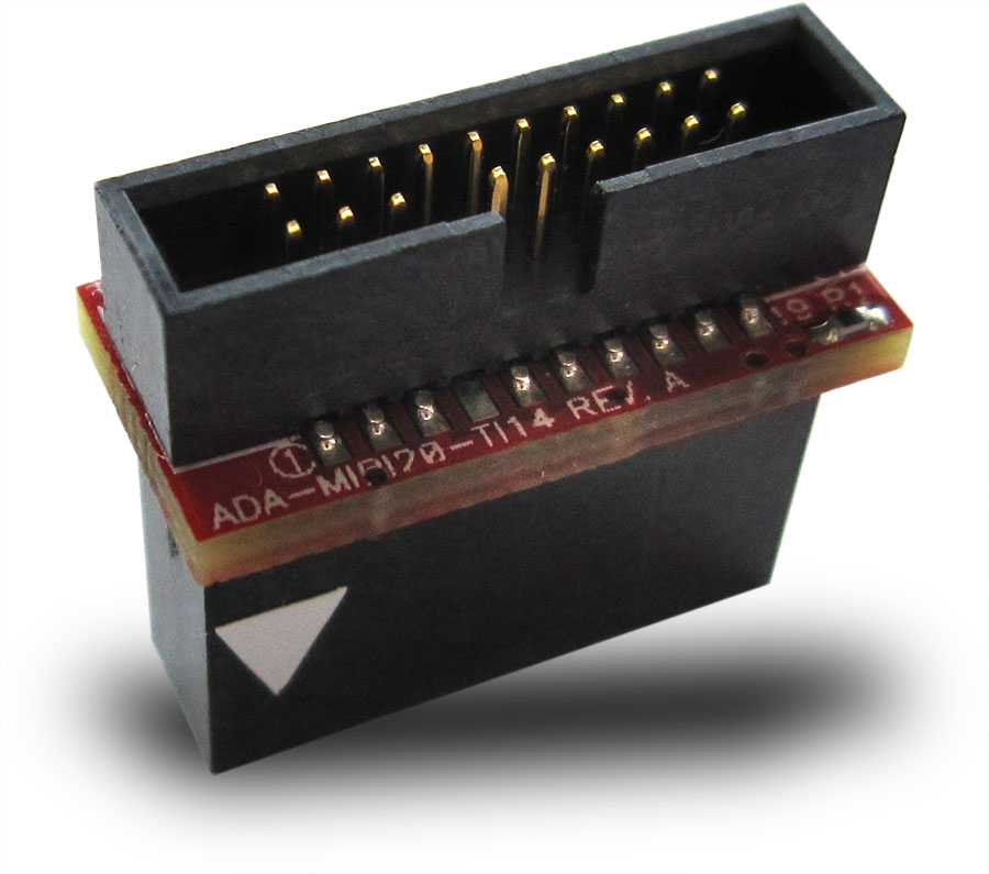
This is a diagram of the ADA-MIPI20-TI14 adapter:
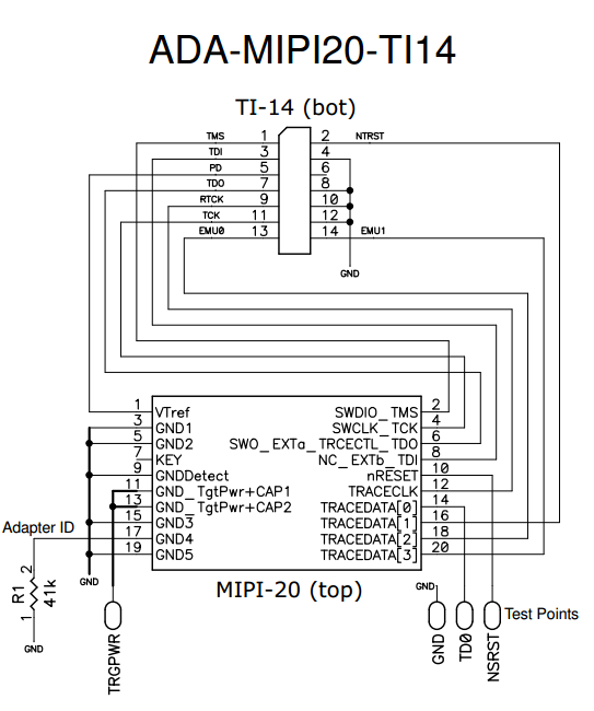
These are the pin definitions for the ADA-MIPI20-TI14 adapter:
Pin | I-jet direction | Name | Description |
|---|---|---|---|
nTRST | Output | Test Logic Reset | Active LOW signal that causes all test and debug logic in the device to be reset along with the IEEE 1149.1 TAP. |
TCK | Output | Test Clock | This is the test clock used for driving the IEEE 1149.1 TAP state machine and logic. |
TMS | Output | Test Mode Select | Directs the next state of the IEEE 1149.1 TAP state machine. |
TDI | Output | Test Data Input | IEEE 1149.1 scan data input to the device. |
TDO | Input | Test Data Output | IEEE 1149.1 scan data output from the device. |
RTCK | Input | TCK Return | IAR Embedded Workbench for Arm: Used only in Adaptive Clocking mode. I-jet monitors RTCK to determine when to send the next TCK. IAR Embedded Workbench for RISC-V: Not used; connected to ground on the target board. |
PD | Input | Power Detect | Should be ties to the I/O voltage of the target device. Used by I-jet to detect whether target power is active and to set the JTAG signal voltage reference for level translators. |
EMU0 | I/O | Emulation 0 | Depending on the device, EMU pins support boot modes and other features. I-jet does not use this pin but it is routed to the TRACEDATA[2] pin on the MIPI20 connector. For proper booting, this pin should be pulled up on the target. |
EMU1 | I/O | Emulation 1 | Depending on the device, EMU pins support boot modes and other features. I-jet does not use this pin but it is routed to the TRACEDATA[3] pin on the MIPI20 connector. For proper booting, this pin should be pulled up on the target. |
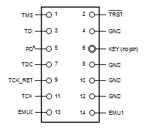
This is the pinout of the target TI14 JTAG header. Pin 6 should be missing to indicate the proper orientation.
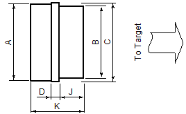
These are the top view dimensions of the ADA-MIPI20-TI14 adapter:

A | 0.74 in (18.9 mm) |
B | 1.0 in (25.4 mm) |
C | 0.76 in (19.4 mm) |
D | 0.062 in (1.6 mm) |
J | 0.38 in (9.6 mm) |
K | 0.80 in (20.3 mm) |
TI14 header information (for target board)
The TI14 header is manufactured by Samtec USA. The model number is TSM-107-01-F-DV. For more information, see the Samtec web page.
The ADA-MIPI20-cTI20 adapter adapts the I-jet standard MIPI-20 cable pinout to the Texas Instruments compact 20-pin JTAG interface used on some newer OMAP, DaVinci, and other TMS320, TMS470, and TMS570 target boards.
The adapter has the MIPI-20 male header on top for connecting the I-jet MIPI-20 cable, and a cTI-20 style female header (socket) on the bottom. The cTI-20 JTAG header is a 20-pin, double-row, high-density 0.05 in × 0.1 in (1.27 mm × 2.54 mm) pitch connector with a key (plug) in position 6 to prevent misconnections. In case the plug is missing, a white arrow on pin 1 of the cTI-20 connector helps you ensure proper orientation.
This is a diagram of the ADA-MIPI20-cTI20 adapter:
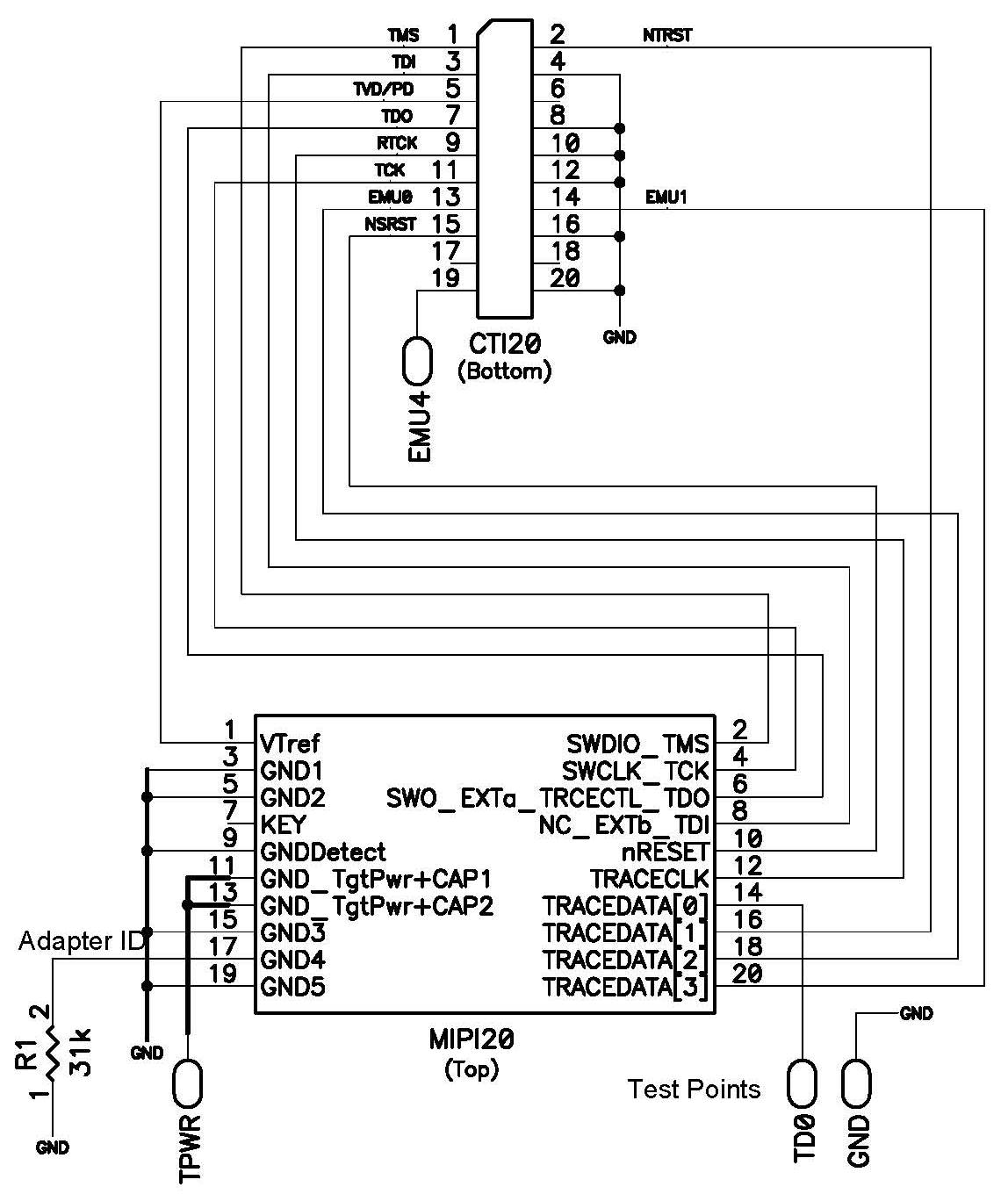
These are the pin definitions for the ADA-MIPI20-cTI20 adapter:
Pin | I-jet direction | Name | Description |
|---|---|---|---|
nTRST | Output | Test Logic Reset | Active LOW signal that causes all test and debug logic in the device to be reset along with the IEEE 1149.1 TAP. |
TCK | Output | Test Clock | Test clock used to drive the IEEE 1149.1 TAP state machine and logic. |
TMS | Output | Test Mode Select | Directs the next state of the IEEE 1149.1 TAP state machine. |
TDI | Output | Test Data Input | IEEE 1149.1 scan data input to the device. |
TDO | Input | Test Data Output | IEEE 1149.1 scan data output from the device. |
RTCK | Input | TCK Return | IAR Embedded Workbench for Arm: Used only in Adaptive Clocking mode. I-jet monitors RTCK to determine when to send the next TCK. IAR Embedded Workbench for RISC-V: Not used; connected to ground on the target board. |
PD | Input | Power Detect | Should be tied to the I/O voltage of the target device. Used by I-jet to detect if target power is active and to set the JTAG signal voltage reference for level translators. |
EMU0 | I/O | Emulation 0 | Depending on the device, EMU pins support boot modes and other features. I-jet does not use this pin but it is routed to the TRACEDATA[2] pin on the MIPI20 connector. For proper booting, this pin should be pulled-up on the target. |
EMU1 | I/O | Emulation 1 | Depending on the device, EMU pins support boot modes and other features. I-jet does not use this pin but it is routed to the TRACEDATA[3] pin on the MIPI20 connector. For proper booting, this pin should be pulled-up on the target. |
nRESET | I/O | System Reset | Active LOW open-collector signal that can be driven by I-jet to reset the device and/or the target board. I-jet senses this line to determine when a board has been reset by the user or by watchdog timer. |
This is the pinout of the target cTI20 JTAG header. Pin 6 should be missing to indicate the proper orientation.
These are the top view dimensions of the ADA-MIPI20-cTI20 adapter:
A | 0.74 in (18.9 mm) |
B | 0.7 in (17.7 mm) |
C | 0.76 in (19.4 mm) |
D | 0.07 in (1.8 mm) |
J | 0.24 in (6.0 mm) |
K | 0.50 in (12.8 mm) |
These are the side view dimensions of the ADA-MIPI20-cTI20 adapter:
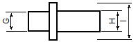
G | 0.19 in (4.8 mm) |
H | 0.2 in (5.1 mm) |
I | 0.36 in (9.1 mm) |
cTI20 header information (for target board)
The cTI20 header is manufactured by Samtec USA. The model number is FTR-110-51-S-D-06. For more information, see the Samtec web page.
The ADA-MIPI20-STSWD6 adapter converts the I-jet standard MIPI-20 cable pinout to the ST SWD 6-pin female connector header.
The target header has pins spaced at 0.1 in (2.54 mm). The adapter has 6-pin female connector plus two wire cables with female connectors for connecting SWD voltage reference input (VTref) and 5V_OUT to optionally power the target board from the debug probe.
This is a diagram of the ADA-MIPI20-STSWD6 adapter:
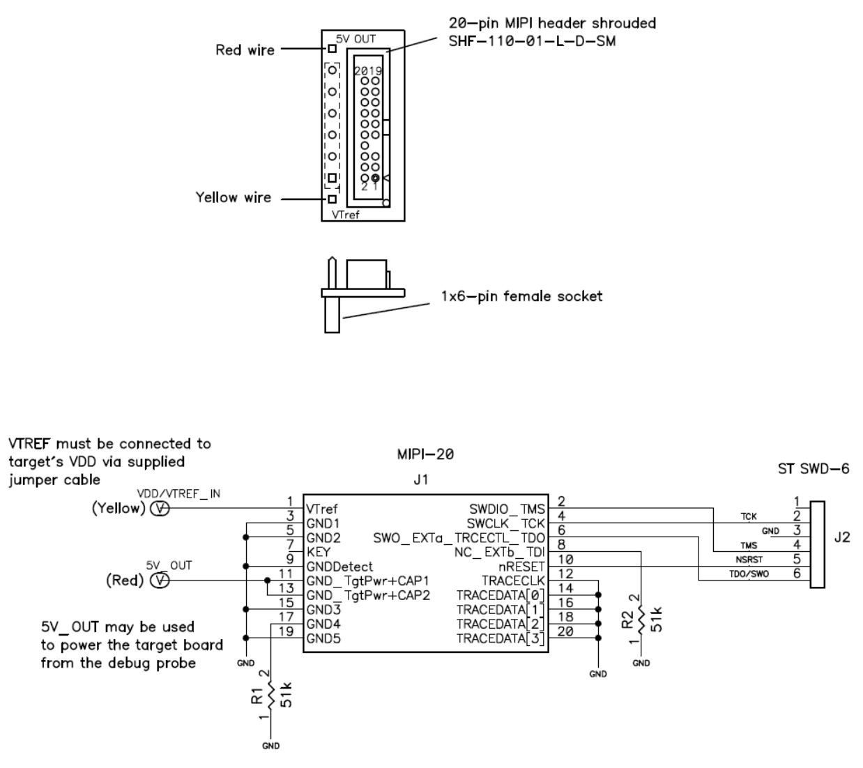
These are the pin definitions for the ADA-MIPI20-STSWD6 adapter:
Pin | I-jet direction | Name | Description |
|---|---|---|---|
1 | NC | No connection - not used. | |
2 | Output | SWCLK/TCK | SWD clock signal to the target CPU. It is recommended that this pin is pulled to a defined state of the target board. |
3 | GND | Common ground. | |
4 | I/O | SWIO/TMS | Bi-directional data pin for SWD. This pin should be pulled up on the target (100k recommended). |
5 | I/O | NSRST | System reset is open-drain and active low and should be pulled-up on the target board. Allows debug probe to reset the MCU if necessary. |
6 | Input | TDO/SWO | SWD trace output port. Optional—not required for SWD operation. |
Yellow | Input | VTref | The target reference voltage. Used by I-jet to check whether the target has power, to create the logic-level reference for the input comparators, and to control the output logic levels to the target. It is normally fed from the target’s VDD voltage. |
Red | Output | 5V Output | This pin can be used for supplying 5V power to the target hardware from I-jet. |
This is a pinout of the ADA-MIPI20-RISCV12 adapter:
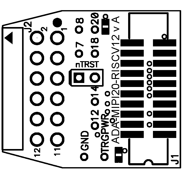
This is a diagram of the ADA-MIPI20-RISCV12 adapter:
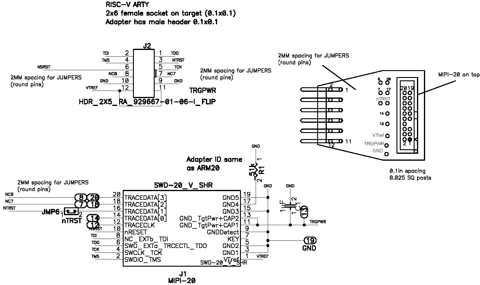
This is the matching between the signal names and pins of connector J2 HDR_2X6_RA_ARTY:
Signal | J1/MIPI20 | J2 |
|---|---|---|
TDO | 6 | 1 |
TDI | 8 | 2 |
NTRST | 16 (jumpered) | 3 |
TMS | 2 | 4 |
TCK | 4 | 5 |
NSRST | 7 | 6 |
NC7 | 7 (jumpered) | 7 |
NCS | 20 (jumpered) | 8 |
GND | 3, 5, 9, 15, 19 | 9, 10 |
VTREF | 1 | 11, 12 |
TRGPWR | 11, 13 | — |
NC12 | 12 | — |
NC14 | 14 |